| Book |
Page |
Context |
 |
 |
Repair 6 49 Oil Filter and Delcotron Adapter g g Cleaning and Inspection 6 49 Repairs g 50 Oil Filter By Pass Valve Replacement 6 50 Stud Replacement 6 50 Engine Rear Housing 6 50 ...
Disassembly g 50 Cleating and Inspection 6 50 Assembly g 50 Repairs g gl Seajl Replacement 6 51 Oil Cooler By Pass Valve Replacement 6 51 Housing Replacement 6 51 Flywheel Housing 6 51 Cleaning |
|
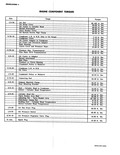 |
50 in ibs 7 13 ft lbs 7 13 ft lbs 7 13 ft lbs 7 13 ft lbs 7 13 ft lbs 15 20 ft lbs 40 50 ...
50 55 ft lbs 15 20 ft lbs r 40 50 ft lbs 20 26 ft lbs 22 2 ft lbs 40 50 |
|
 |
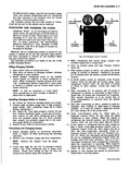
Capacity TYPE OF LENGTH CHARGING CHARGE OF TIME RATE Boost Charge for Light Load Test 20 Minutes 50 Amps Slow Charge 24 Hours 4 Amps Fast Charge 1 1 2 Hours 40 50 Amps Quick ...
Boost 30 Minutes 40 50 Amps Dry Charge Warm up Boost 10 Minutes 15 Amps |
|
 |
50 49 48 47 f 46 45 44 43 42 41 40 Fig 7B 1 Corvpir Four Speed T nsm l Clutch Gear Bearing Cover 15 lst Blacker Ring 2 Clutch Gear 16 Reverse Shifter ...
chronizer Hub 49 Clutch Gear Bearing 38 ynchrdnizer Key Snap Ring 39 ReverseF Shifter Head 50 Snap Ring Input 40 1 2 Shift Fork Shaft Bottoming Stop 41 3 4 Shift Fork |
|
 |
hole through the center of the spindle and attach the bracket with two bolts Torque to 30 50 lbs in 4 Assemble backing plate to steering knuckle with brake anchor bolt 5 Assemble steering ...
steering arm bolts and lock nuts through backing plate steering knuckle and steering arm Tighten nuts 40 50 lbs ft 6 Tighten brake anchor bolt to 70 90 lbs ft 7 Install brake shoes |
|
 |
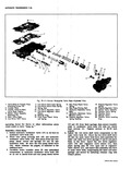
01bl 50 48 52 49 46 57 ss 59 rglide Exploded View 30 Transmission Throttle Valve 44 Of I Pan Gasket Leveir and Shaft Assembly 45 Oi I Pan 31 Monlwl Valve Lever ...
Servo Piston Retaining Inner Lever Clip 33 Govlmor Gear Thrust 49 Low Servo Piston Spacer 50 Low Servo Piston Ring 34 Governor Drive Gear 51 Low Servo Piston Cushion 35 Turbine Shaft Front Bushing Spring |
|
 |
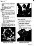
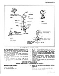
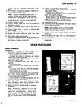
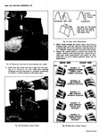
ring into the groove using tag wire fig 49 or a plastic com pression ring fig 50 If tag wire is used make one twist with pliers and bend the wire to form it along ...
assembly in approximate installed position add oil into oil inlet until it flows from drain r Fig 50 Compressing Ring Using Plastic Installer Ring |
|
 |
seat the seal quickly Itemove the guide pins and install five rear pump mounting bolts fig 7E 50 securing to 9 11 ft lbs A l i a1f 7a 7 Fig 7E 50 Measuring Rear |
|
 |
50 45 44 3 3w 38 34 I 3 Fig 7A 13 Manual rarun 1 Input Shaft 16 Clutch Gear 2 2 Mairlshaft Bearing 17 Snap Ring 31 3 Moinshaft Bearing Retaining 18 Clutch Gear ...
Needle F First and Reverse Fork Bearings and Thrust 3 Transmission Case Washer Pipe Plu 2 Used 50 Thrust Washer Detent Gop Gasket 51 Reverse Idler Gear Bearing Race I Detent Cap 52 Reverse Idler |
|
 |
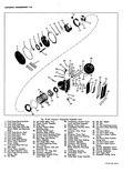
50 49 41 40 39 j 34 33 T i 1 O n 1 0 P91 To 14 7 1 W 51 48 47 46 45 44 43 42 38 37 Fig 39 Six Cylinder ...
Ring Plate Assembly 48 Strainer Screen 37 Rear Thrust Race and 49 Compressor Rear Head Bearing Pack 50 High Pressure Relief 38 Rear Cylinder Half Valve and O Ring 39 Oil Inlet Tube 51 Rear |
|
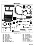 |
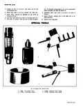
linder Bore 22 J 1264 Torque Wrench 0 200 Ft Lb J 8058 Torque Wrench 0 50 Ft Lb J 5853 Torque Wrench 0 100 In Lb 23 J 8354 Stud Replacer Tool |
|
 |
operation 5 Note unusual noises or vibration that would warrant further inspection of Turbocharger ajar Inspection Every 50 000 miles or if trouble is suspected in urbocharger it should be inspected and serviced as Alows |
|
 |
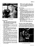
hose or let stand until dry 7 Fill body of cleaner with one pint of SAE 50 engine spECrai n 3 1 4 Fig 67 Engine f 1 J 7825 Air Cleaner Tester |
|
 |
tunnel from plate w HOUSING A 8 0 LEVER ASSBY SPRING VIEW C 10700 MODELS CUP SEAT 50 MAX 10100 500 40 MAX 10700 FRONT FACE OF FULCRUM BLOCK t LINE OF FRONT rACHING STUDS |
|
 |
plalte to modulator valve body 18 with two clutch he d screws 1 Tighten screws to 38 50 inch pot nds M 4 In4tall the low drive shift valve components in the m in valve |
|
 |
bolts Note that longer bolt is installed in forward hole 2 Install nuts and torque to 40 50 ft lbs Use only the SPECIa 2 3 i 6 Fig 26 1 J 6627 Pitman |
|
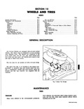 |
snap on type hub caps or wheel trim covers The tire size for all models is 6 50 x 13 4 ply rating The spare tire fig 1 is mounted in the engine compartment |
|
 |
adjust as required Electrical contact should be made when the brake pedal is depressed 38 to 50 inch from fully released position DIMMER SWITCH REPLACEMENT Fig 14 1 Lift interior floor mat 2 Remove |
|
 |
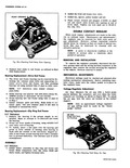
time place the fron ball and seat and the rear ball only over the wobble plate fig 50 Hold front thrust bearing pack tight against wobble plate hub while lifting shaft 9 Repeat this operation |
|
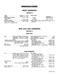 |
Sleeve Lock 20 25 ft lbs Differential Cover 130 230 in lbs Differential Carrier to Transmission 35 50 ft lbs USPENSION Bolt Torques Rear Wheel Spindle Support to Torque Control |
|
 |
Bath Type Check every 6 000 miles Clean if necessary and refill with engine oil SAE 50 when temperature is above freezing and SAE 20 below freezing BATTERY Every 6 000 miles clean |
|
 |
insert allen wrench into opening at end of drive shaft Tighten one lock shaft nut to 50 60 ft lbs fig 15c DOUBLE CONTACT REGULAR While i most regular adjustments are made on the vehicle |
|
 |
vehicle equipped with Powerglide becomes disabled and requires towing or pushing speed must not exceed 50 MPII Bottj manual and Powerglide transmissions should be towed in neutral only with parking brakes fully released Wheh towing |
|
 |
refrigerant Control Valve 4 and Low Pressure Control 1 Watch low side gauge and keep gauge below 50 psi by regulating refrigerant Control Valve 4 Closing valve will lower pressure This is to prevent liquid |
|
 |
Stator Cam Race 49 Low Servo Piston Cushion 35 Converter Hub Seal Spring 36 Stator Shaft 50 Low Servo Piston Return Spring 37 Pinion Shaft Rear Oil Seal 51 Clutch Drum Piston 37A Rear Selective |
|
 |
Reverse Piston Assembly 7 46 Converter 7 48 Planet Carrier Assembly 7 48 Assembly of Transmission 7 50 Front Pump Thrust Washer Determination 7 51 Transmission Removal and Installation 7 54 Diagnosis Guide |
|
 |
rust Races 0 nnd Beorin Holding Fixture J 9396 Compressing Fixture 1 9397 Fig 50 Installing Piston Front Ball and Seat and Rear Ball CCNtVAIR SHOP MANUAL |
|
 |
main valve body and secure with two remaining clutch head screws 1 Tighten screws to 38 50 inch pounds 9 Install manual valve 24 in main valve body then check shift cable adjustment as described |
|
 |
Pinion Bearing Remover 8 1313 0 150 ft Ibs Plates Used with 9 J 5853 0 50 n Ibs J 0358 1 Holder 10 J 8092 Driver Hand 3 J 2619 4 Positraction Axle threo |
|
 |
Start engine check fog leaks and perform necessary adjustments ROCEDURES I 75 3 HOLES HOLE 1 50 m 31 25 HOLE z HOLES |
|
 |
spindle and attach the bracket to the steering knuckle with its two attaching screws 30 50 lbs in torque 3 Reinstall the grease cap as follows set the cap in place over |
|
 |
form a frijCtion brake turn the ring gear back and forth with a rench fig 50 on the ring gear mounting bolts until a definite contact pattern is formed on the pinion 4 Inspect |
|
 |
bleeder equipment is at operating level and that the equipment is capable of exerting 30 to 50 lbs hydraulic pressure on the brake system 3 Position one end of bleeder hose on left rear wheel |