| Book |
Page |
Context |
 |
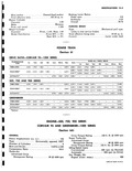 |
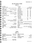
Push rod travel 1 32 Wheel Cylinder Diameter Front 1 125 Rear 1 0 Brake Distribution Front 50 2 Rear 50 Jo 2 POW Se DRIVE RATIO CORVAIR 95 1200 SERIES TRANSMISSION ...
Drive TYPE THREE SPEED 3 50 1 1 99 1 1 00 1 FOUR SPEED 4 26 1 2 55 1 1 68 1 1 00 1 AUTOMATIC ...
SERIES THREE SPEED 3 50 1 1 99 1 1 00 1 FOUR SPEED 3 65 1 2 35 1 1 44 1 1 00 1 AUTOMATIC 4 73 1 1 00 1 GREENBRIER THREE |
|
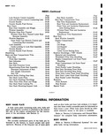 |
Panel Moulding 10 49 Rear Door Lower Outer Panel Moulding 10 49 Rear Fender Lower Moulding 10 50 Bumpers 10 50 Front Bumper 10 50 Rear Bumper 10 50 Special Tools 10 70 4FORMATION such |
|
 |
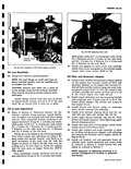
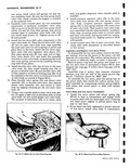
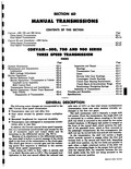
front of the case REVERSE IDLER f GEAR REVERSE SHIFT FORK REVERSE SHIFTER LEVER Fig 6D 50 Installation of Reverse Shifter Lever Shift Fork and Reverse Idler Gear 6 Place reverse shifter lever ...
50 on pin in case with tapered end away from the reverse inhibitor 7 Place the reverse idler gear shift fork in the case with its pin toward the front fig 6D 50 Engage ...
idler gear shift fork fully rearward engage the reverse idler gear to the shift fork fig 6D 50 Then align the Woodruff key groove in the idler gear shaft with the keyway in the rear |
|
 |
Series 3 Speed 4 sp 3 Speed 4 Speed 3 sp a 4 speed First 3 50 1 3 65 1 3 50 1 4 27 1 3 50 1 4 26 1 Second |
|
 |
GEAR AND CONTROL RATIOS 3 Speed Manual Transmission 1st Gear 3 50 1 2nd Gear 1 99 1 3rd Gear 1 00 1 Reverse 3 97 1 4 Speed Manual Transmission 1st Gear ...
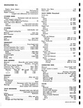
Type Tubeless Tyrex Size and Ply Rating Station Wagons 7 00 x 13 4 All Others 6 50 x 13 4 Pressures Front Rear Hot 18 psi 30 psi Cold 15 psi 26 psi Spare |
|
 |
Removed 7 Install the valve rocker cover with a new gasket and torque cover screws 30 to 50 in ibs 8 Install the oil cooler with new seals and torque mounting bolt ...
assembly fig 6A 14 Raise engine assembly and install the rear mounting nut washer and torque nut 50 to 60 ft lbs Install cotter pin 10 Install left right and center shield seals refer |
|
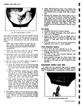 |
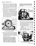
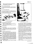
into hole of awl needle with end of rubber strip extending beyond the needle See Figure 3 50 c Pull needle through tire with pliers Filler Rubber will remain in the puncture Cut off excess ...
tire repair or some type of misalignment Consequently if front end in r s Ir ftg 3 50 Installing Filler RebMr in Hole |
|
 |
covers and carefully attach valve cover and gasket to the cylinder heads torque valve cover screws 30 50 in lbs Oil Filter and Generator Adapter 43 Install a new oil filter and generator adapter gasket ...
generator adapter with adjusting slot towards the flywheel end of engine shown in Figure 6A 35 50 Install coil bracket coil and generator brace on cylinder head Install generator and torque bolts as outlined |
|
 |
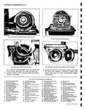
generator Hot output 30 amps 14 volts and 2900 rpn Field current draw 1 50 1 62 amps 12 volts 80 I Current draw when run as motor Average 4 8 amps ...
BTDC 13 BTDC 0 rpm 0 2 1400 rpm 0 2 700 rpm 50 |
|
 |
transmission to a horizontal position then install the low band apply strut and reaction strut fig 6E 50 When the low band linkage is all installed snuggly tighten the low band adjusting screw to prevent ...
SCREW REACTION STRUT LOW BAND r APPLY STRUT Y1 LOW SERVO PISTON SHAFT A r Fig 6E 50 Low Band Components Installed 13 Front Selective Thrust Washer Determination Prior to reinstallation of the front pump |
|
 |
Flywheel 6A 49 Pistons Cylinders and Connecting Rods 6A 49 Crankcase Cover and Blower Bearing 6A 50 Oil Pump Screen and Tube Assembly 6A 50 Cylinder Head 6A 51 Push Rod Oil Drain Tube |
|
 |
cylinder heads 4 Install valve rocker covers with new cover gaskets Torque valve rocker covers 30 to 50 inch pounds HYDRAULIC VALVE LIFTERS Hydraulic valve lifters very seldom require attention The lifters are extremely simple |
|
 |
50 w 14 25 45 60 70 N 20 30 5 70 80 13 O 75 90 105 1Ar20 |
|
 |
place on mounts then install nuts Torque front mounts to 60 80 ft lbs and rear mount 50 60 ft lbs Install cotter pins at both mountings NOTE If engine front mounting bracket and shims |
|
 |
50 |
|
 |
EATER tion 11 IGNITION COIL RATING Primary 4 ohm Secondary 4 000 ohm SOLENOID COIL RATING 50 ohm FUEL PRESSURE 4i z 5 lbs CORVAIR SHOP MANUAL |
|
 |
Lamp Heater Control Panel Lamp 3 AG AGC 3 AMP ELECTRICAL Candle Power Number 37 Watt 4002 50 Watt Sealed Beam 37 Watt 4001 Sealed Beam |
|
 |
Attachment 60 80 in Ibs le 60 BOin Ibs Cover 30 50 in Ibs to R H 7 13 ft tbs eer to Crankcase 7 13 ft tbs apterto Crankcose 7 13 ft lbs Generator |
|
 |
Material Foot Alloy cast iron Sleeve Steel Plunger and Push Rod Seat Steel Rocker Arm Ratio 1 50 Valve Lash Zero VALVE TIMING Theoretical Turbo Air Inlet Opens 43 BTC Closes 93 ABC Exhaust Opens |
|
 |
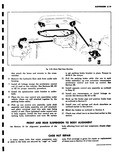
installation of door coat attaching surfaces of hinges with heavy bodied sealer as indicated in Figure 10 50 2 With aid of helper reinstall door to hinges Align hinges within marks and tighten screws Check |
|
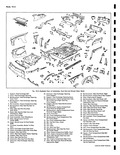 |
Rear End Panel License Plate linge Lower 49 Filler Rear End Outer Panel Right ne Compartment Cover 50 Plate Rear Bumper Mounting ngi 51 Filler Rear End Outer Panel Left Upper 52 Panel Rear |
|
 |
decribed below and install starting motor Pinion Clearances The pinion clearance should be checked fig 8 50 after motor has been reassembled If clearance is not within specified limits 010 140 it may indicate excessive |
|
 |
steady press on the pulley if interference is encountered d Torque the pulley attaching nut to 50 60 ft lbs r BACK UP PLATE BEARING CAP KEY GENERATOR PULLEY |
|
 |
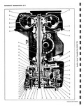
50 48 54 52 56 49 46 57 47 58 o o P 59 Pow rglide Exploded View CORVAIR SHOP MANUAL |
|
 |
Servo Piston Retaining Clip Inner Lever 49 Low Servo Piston 33 Governor Gear Thrust Spacer 50 Low Servo Piston Ring 34 Governor Drive Gear 51 Low Servo Piston Cushion 35 Turbine Shaft Front Bushing Spring |
|
 |
main valve body and secure with two remaining clutch head screws 1 Tighten screws to 38 50 inch pounds 9 Install manual valve 24 in main valve body then check shift cable adjustment as described |
|
 |
50 |
|
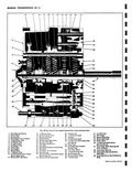 |
Synchronizer Hub 49 Clutch Gear Bearing Selective 38 Synchronizer Key Snap Ring 39 Reverse Shifter Head 50 Snap Ring Clutch Shaft bottoming 40 1 2 Shift Fork stop |
|
 |
bolt on top of body mounting bracket 9 Install mount retaining washer and castellated nut and torque 50 60 ft lbs and install cotter pin 10 Install engine rear center shield |
|
 |
crankshaft pulley bottoms in place Back crankshaft pulley retaining bolt off one turn and torque 40 to 50 ft lbs Remove wooden wedge from crankshaft NOTE Do not drive crankshaft pulley on crankshaft this will |
|
 |
Seem Mevnting to get parking brake bracket in place Torque to 40 50 ft lbs torque 11 Pull the parking brake cable the one to each brake assembly up over automatic transmission accelerator control |
|
 |
Raise engine and install rear engine mount Torque rear engine mount 50 to 60 ft lbs and install retainer cotter pin 6 Tighten front engine mount nuts 60 to 80 ft lbs torque |
|
 |
Raise engine and install rear mount and torque mounting nut and bolt 50 to 60 ft lbs Install cotter pin 4 Install rear shield seal center shield and seal Install engine left lower shroud |
|
 |
Torque 50 60 ft lbs and install cotter pin 9 Install engine rear center shield OII FILTER AND GENERATOR ADAPTER Rerr wal 1 Release pulley belt tension at idler pulley and emove blower pulley belt |
|
 |
retainer bolts from mounting and remove mount 6 Install new mount with bolts and torque 40 to 50 ft lbs 7 Raise engine to body mounting bracket and install castellated nut to mounting bracket bolt |
|
 |
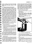
operating level and that the equipment is able to exert at least 30 to 50 Ibs hydraulic pressure on the brake system 3 Remove bleeder valve dust cover Install Tool J7647 on bleeder hose Position |
|
 |
commercial steering gear has 54 balls ir tead of 48 St ering Gear Assembly fig 4 50 Mter a major service overhaul where all of the origin l factory installed lubricant has been washed |
|
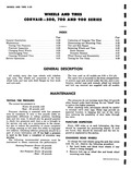 |
Testing for Tire Noise 3 28 iESCRIPTION The tires used on all models are 6 50 x 13 4 ply The spare tire is mounted in the front compartment A scissors type jack stowed under |
|
 |
remove gear from crankshaft a hydraulic press is required J 7048 J 3ss 1 Fig 6A 50 Remevinp Crankshaft Gear Ma i Bearings 52 Remove main bearing inserts from each half of rankshaft by rotating |
|
 |
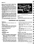
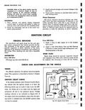
filled with light engine oil evei L000 miles fig 2 6 Distributor cap should be removed every 50 miles Apply a small amount of Delco Remy cam ar f ball bearing lubricant or other suitable |
|
 |
CsENERAL CONTENTS Cc vair 500 700 900 Series Cc wair 95 and Greenbrier 1200 Series CORVAIR 50 Pag Ei One 2 rankcase Oil 2 Crankcase Capacity 2 First 1000 Miles 2 After 1000 Miles |
|
 |
Reai 1 J 1264 0 200 Ft Lb Torque Wrench 2 J 5853 0 50 In Lb Torque Wrench 3 J 8362 Pinion Turning Adapter 4 J 8001 KMO 30 Dial Indicator |
|
 |
TAIL w STOP DOME r CIO L C 1 lT R 4 ie NE AL BOW GL 50 |
|
 |
Face angle 45 Cutter diameter 1 50 Exhaust Material High alloy stee Overall length 4 494 4 51 Overall head diameter 1 235 1 24 Seat angle in head 45 Stem diameter 001 taper |
|
 |
Removed Valve Lash 4 i istall valve cover and gasket Torque valve cover rews 30 to 50 in lbs VAL E SPRINGS Rem val and Installation 1 emove valve cover and gasket 2 1 emove |
|
 |
Engine flex Plate 49 Low Servo Piston Cushion 34 Stator Cam Race Spring 35 Converter Hub Seal 50 Low Servo Piston Return Spring 36 Stator Shaft 51 Clutch Drum Piston 37 Pinion Shaft Rear |
|
 |
WHEEL BEARINGS Type Double row spherangular roller bearing lubricated for life TIRES Size 6 50 x 13 4 Ply Type Tubeless Inflation COLD HOT Front 15 18 Rear 26 30 Spare Tire Inflate |
|
 |
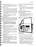
open circuit or the valve is stuck on the valve seat The coil should have approximately 50 ohm resistance when checked with an ohmmeter or it should show about 24 amps at 12 volts when |
|
 |
power flow sequence is identical to the conven tional three speed transmission Gear ratios are 3 50 1 in first 1 99 1 in second ant 1 1 in third Reverse ratio |